Chances are you just received your new level sending unit and you’re looking to install it in your tank but don’t know where to begin. This guide will help make the situation much easier walking you through the ten steps of installing your level sending unit as well as possible issues you may have along the way.
Note:
- If you are unsure how to perform any of the detailed procedures, seek professional assistance.
- Warning! Gasoline is extremely flammable. Keep tank area free from sparks and flames.
- Avoid using power tools around fuel vapors which are easily combustible.
What You’ll Need:
- Tape measure (for all KUS Senders)
- 5/16” HEX head screwdriver / socket (For SAE 5 Hole Mount units)
Step 1
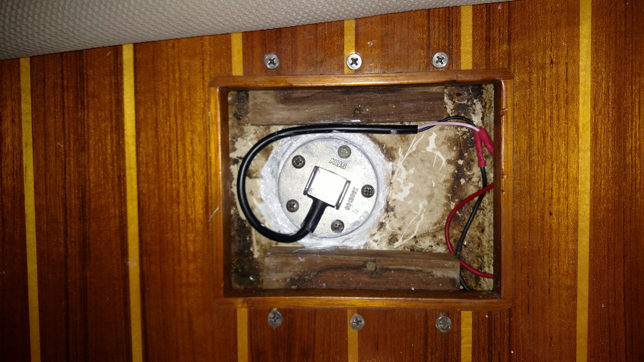
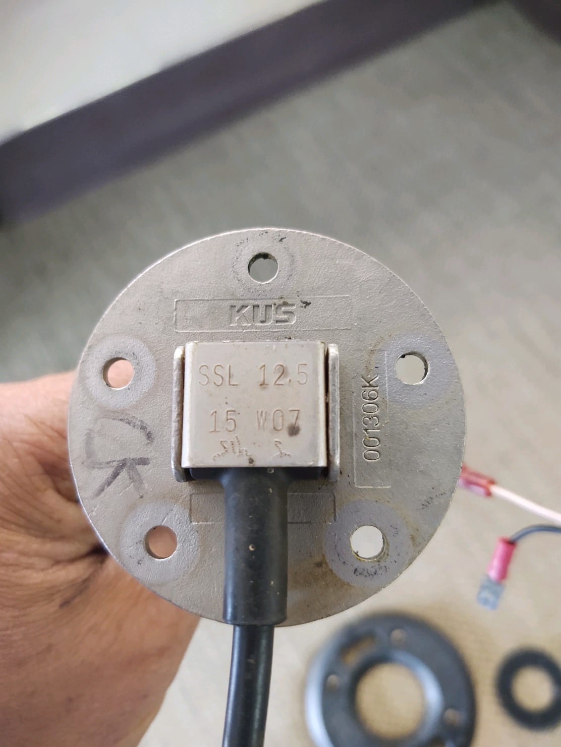
Replace existing sender by removing the previous sending unit if you have one. Make sure all power is turned off and all devices are unplugged then, using your 5/16” HEX head screwdriver, unscrew the five screws from the SAE 5-hole mount in a star shaped pattern. The SAE 5-hole bolt pattern is not evenly spaced, it can only be aligned one way. Match the lead hole on the tank with the lead hole on the sending unit, this would be the hole that is opposite of the electrical lead egress.
Step 2
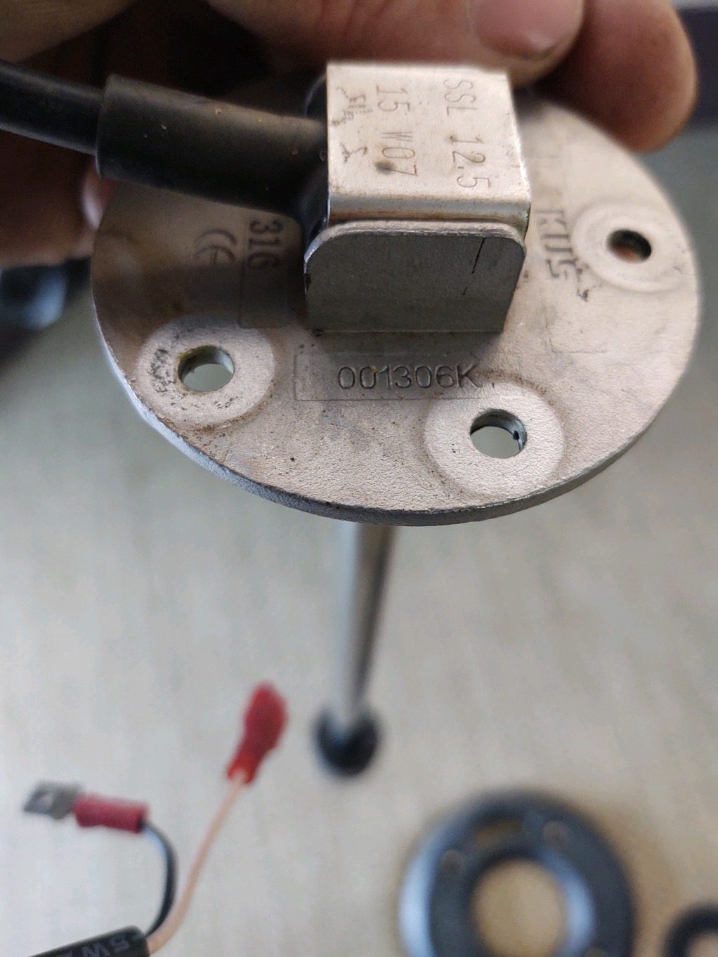
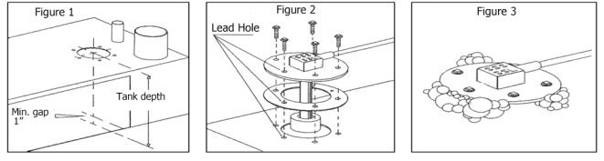
Determine the proper sending unit length for your tank by measuring from the inside bottom to the outside top of the tank. A minimum 1” clearance must be maintained between the tank bottom and the float retaining collar. Clearance must also be accounted for the adjacent side or the baffle of a tank when determining the proper length.
You can also measure the length of the current sending unit to determine the new sending unit length. Failure to maintain proper clearance may result in the unit to malfunction, cause tank damage, and will void warranty of the unit.
Step 3
Order your level sending unit and be sure to select the proper length and type. Depending on your application solution you may also need to order a gasket mounting kit to prevent any leakage.
Step 4
Once you receive your level sending unit and gasket mounting kit you can begin the installation process. Start by sliding the gasket over the down tube, then align the 5-hole screw pattern to fit flush against the underside of the mounting plate. Remember, the screw hole pattern is not symmetrical; there is only one way to properly align the gasket. The lead hole is 180 degrees from (opposite side of) the sender wire egress.
Step 5
Position the new level sending unit above the tank, aligning the screw hole pattern in the mounting plate with the hole pattern at the top of the tank. Align the sender lead hole with the tank lead hole (marked previously).
Step 6
Install the level sending unit (with the aligned gasket) by inserting the down tube into the tank. Make sure to empty the tanks of fuel and fumes before installation.
Step 7
Secure the level sending unit to the tank by tightening the mounting screws into place using a star shaped pattern. Do not over-tighten, this weakens the seal. Excessive torque or re-tightening can cause the gasket underneath the sender head to be over-compressed or pinched in at least one area, dramatically reducing the service life of the gasket. This could result in failure (leakage), while in service.
Step 8
To ensure the level sending unit is properly installed, a leak test needs to be conducted. Pressurize the tank to 3 PSI and look for bubbles using soapy water around the seal (see Figure 3 below). If bubbles are present this means that the SAE 5-hole mount screws are not tight enough. Proceed to tighten these screws in a star shaped pattern and rerun the leak test until bubbles are no longer present.
Step 9
Once the level sending unit is installed, it needs to be connected to a gauge. The below wiring should be followed:
1) Connect ground (pink) wire from the KUS sending unit to a common grounding hook-up.
2) Connect (black) wire from the KUS sending unit to gauge hook-up. If your gauge has color coded hook-ups, maintain this coding as you connect the sender and ground wires.
Step 10
Turn on the power to the level sending unit and gauge. Adjust the float and pay attention to the gauge, if the gauge has a reading that correlates to the position on the float then the level sending unit and gauge are functioning properly. If not, this may mean that the level sending unit or gauge is not functioning properly. See our previous post on troubleshooting your boats fuel level sender to address the issue.
Let KUS Walk You Through the Level Sending Unit Installation Process
You can count on KUS customer service and sales representatives every step of the way from initially selecting a liquid level sending unit to guiding you through the installation process. Many of the worlds leading marine companies rely on KUS for affordable yet reliable level sending units that will stand the test of time given different operating environments. Get in touch with KUS today to learn how we can be your marine level sending unit supplier!